burning plugs & wires [customer case]
The mobile network operator was losing −48 V DC power feeds to radio units — both 4G RRUs and 5G active antenna units — across a large portfolio of macro sites. Conductors were being found charred and connector bodies melted, in some cases fused onto the cable. The failures recurred at the same positions after replacement.
Each event meant an out-of-hours call-out, a coverage outage, and often a destroyed radio unit as well as a destroyed cable. On tall towers in forested and agricultural terrain it also meant a credible fire-ignition risk. C12 was called in to establish why it kept happening.
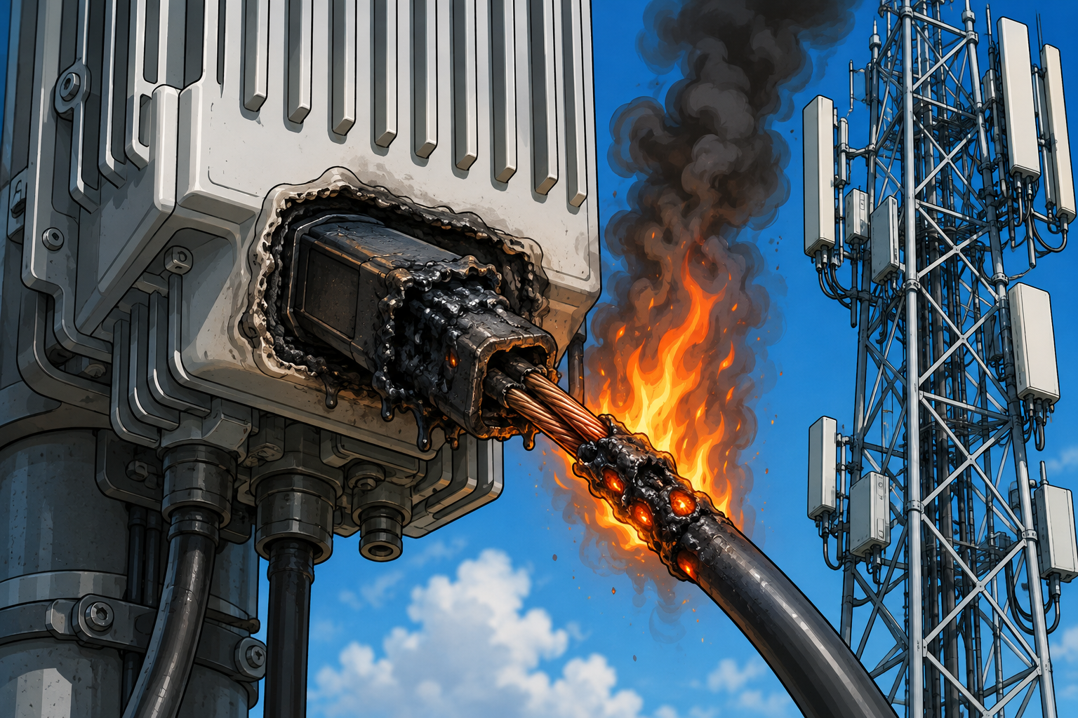
Root cause: The power feeders had been sized against the current the equipment was observed to draw, not against the rated power of the equipment they feed — and the installation derating factors had not been applied.
Ampacity: After derating, the installed cable was rated well below the load. The installed feeder was UL 2586 10 AWG (≈ 6 mm²), rated 41 A at reference conditions. The installation is nothing like reference conditions. Applying the correction factors required by IEC 60364-5-52 and HD 60364-5-52, and mirrored in NEC 310.16:
Final ampacity = Nominal × Ca × Cg × Ci × Cs
Ca — ambient temperature: 0.80 (Cables run on steel structure in direct sunlight)
Cg — grouping: 0.75 (Approximately eight feeders bunched on the same route)

Result: 41 A → 24.6 A (Installation conditions remove roughly 40 % of the cable’s tabulated rating)
                         ....under the same conditions: 10 mm² derates 61 A → 36.6 A, and 16 mm² derates 81 A → 48.6 A.
The real load exceeded that derated figure (26.4 A) whenever the radios were busy: We ran forced throughput tests on individual units and measured current at the feeder.
The 5G active antenna unit under normal traffic drew 14 A and during the load test 31 A. This unit was rated at 36 A on its nameplate. The 4G mid-band under normal traffic drew 15.0 A and during the load test 28.0 A This unit was rated at 33 A on its nameplate. The 4G low-band antenna unit under normal traffic drew 7.0 A and during the load test 9.0 A. This unit was rated at 11 A on its nameplate.
The 5G unit drew 2.2 times its quiescent current under load — and 125 % of the derated cable rating. The 4G mid-band unit reached 114 %. Measured against nameplate the margin is worse again: the installed radio types are rated from 10 A up to 50 A per unit. A conductor good for 24.6 A in situ is roughly half of what the largest unit is entitled to draw.
At site level, a fully loaded four-sector configuration carrying 700/800/900 + 1800/2100/2600 + 5G draws approximately 124 A at 48 V (≈ 6.0 kW) on battery, and approximately 144 A at 50 V (≈ 7.2 kW) on rectifier supply. The distribution has to be designed for that, not for a quiet Sunday morning.
Voltage drop was governing before ampacity — and was heating the cable: IEC/BS design practice allows 3 % drop for lighting and 5 % for other final circuits. On a 53 V DC system that is 2.65 V; on 57 V, 2.85 V. At 48–57 V there is no headroom — a drop that would be negligible on a 400 V AC circuit is a large fraction of the supply here.
The energy lost in that drop does not disappear. It is dissipated as heat inside the cable, along its whole length: A 30 A load with a 4 V drop becomes a 120 W heater installed inside the cable route.
Sizing against the 2.65 V limit at 45 °C conductor temperature (ρ = 0.01922 Ω·mm²/m), the cross-section required for 25 A is 4.35 mm² over a 12 m run but 15.23 mm² over 42 m. Run length, not current alone, was decisive — and 6 mm² satisfies the limit only on sites with the shortest runs.
The cost that was already being paid
The same undersizing that was burning connectors was also being paid for continuously, as resistive loss in the copper. Across the operator’s portfolio — roughly 100km of radio feeder over several hundred macro sites — at network-average feeder loading:
A conductor with
6 mm² (as installed) of a 1 meter distance on a 20A load experiences losses of 2.33 W/m.
A conductor with 10 mm² of 1 meter distance on a 20A load experiences losses of 1.4W/m.
A conductor with 16 mm² of 1 meter distance on a 20A load experiences losses of 0.8W/m.
Upgrading the installation to 16 mm² reduces the losses by 1.45W/m at 20 degrees Celsius. On a 100km radio feeder cable across all installations this becomes 153kW every hour and results 1.3GWh. A €0.33 cost per kWh results in €429,000 savings PER YEAR from the reduction in your energy cost before counting any of the avoided failures, avoided call-outs and overtime, avoided replacement of damaged radios and cable, or the reduced fire exposure.
Conclusions
1. The burnt connector was a symptom, not the cause. Re-terminating to specification without upsizing the conductor would have returned the fault. Both corrections were needed.
2. Infrastructure must be designed to equipment nameplate rating. A commissioning survey taken at low traffic understates 5G AAU current by more than half. A spot measurement is not a design load.
3. Derating factors are not an optional refinement. A steel structure in direct sun with bunched feeders removes about 40 % of a cable’s tabulated ampacity. Omitting Ca and Cg is precisely what turned a nominally adequate 41 A cable into a 24.6 A cable feeding a 30 A load.
4. On 48 V DC, voltage drop usually governs before ampacity once the run exceeds roughly 20 m. Size on the stricter of the two checks, evaluated at 45 °C rather than 20 °C. Increasing temperatures from undersized cables increase the internal resistivity of the cables and create a vicious cycle which many times results in fires, wire, plug, equipment melting and extensive energy losses.
5. The loss is a running cost, not only a risk. On this network the energy argument alone carried the business case for re-cabling.
Warnings — worth checking on your own sites
• Do not accept a “normal conditions” reading as the design load. Measure under a forced throughput test and cross-check against nameplate.
• Look above the connector, not only inside it. Discolouration on the conductor upstream of the termination points to an undersized cable. Damage confined to the termination points to workmanship. The two require different remedies.
• Treat repeat “no fault found” RF alarms as a power symptom. A radio browning out on undervoltage derates or resets long before anything burns.
• Grouped routes are the worst case and the easiest to miss. Every cable added to a bunch derates every other cable already in it. Adding 5G to an existing route silently reduces the rating of the 4G feeders beside it.
• Tall towers in forested and agricultural terrain carry the highest consequence. This is an ignition scenario, not only an equipment-loss scenario.
• Make thermography an acceptance test, not only a maintenance activity. A hot termination found at handover is a defect. Found two years later, it is a failure.
The first finding was not the answer: Inspection did confirm a workmanship problem: the cable was not being prepared and entered into the connector to the manufacturer’s specification — strip length and conductor entry were both out of tolerance. That is normally where an investigation of a burnt termination stops. We did not stop there, for two reasons. The failure rate was far too high to be explained by isolated poor terminations across many crews and many sites. And the burning was present on the conductor above the connector, not only inside it. Damage upstream of a termination is the signature of a conductor running hot along its length — a sizing problem — rather than a joint with high contact resistance.
A bad crimp burns at the crimp. A cable burning along its length is telling you something else.